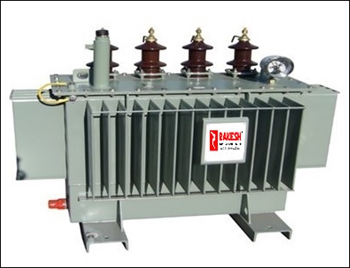
Earthing/Grounding Transformer
The Earthing transformer is one of the the must to have equipments for those distribution stations, which deals with delta connected transmission lines. The power system transmission lines are generally made up with three phases, so three individual wires or conductors are used to transmit the three phase power from the generating station to the distribution substation.
Three phase system is more economical and profitable than single phase or two phase system. The three phase power transmission system is termed as “three phase three wire system” of power transmission. The three wire system is most suitable for providing power in the industrial belts. Because, all the three wire systems consist of only phase wires, so it delivers the phase to phase voltage to the load, that is VPh. Suppose each phase carries 220 Volt. Then in distribution station, the phase to phase voltage will be very high, in order of 440 volt, which is generally used in industrial belts. But, for domestic purposes, the voltage level must be in order of 230 Volt. This necessitates the three phase four wire system, where the additional wire is used as the system neutral. The phase to phase voltage (called as line voltage) is √3 times of phase to neutral voltage (called as phase voltage). Adding the neutral wire serves many purposes.

A three phase four wire system is able to deliver both line voltage for industries and phase voltage for domestic uses. So, it increases the scope of power distribution conveniently. In star connected transmission lines, the neutral point is accessible for further using. Or in other words, a star connected transmission line is three phase four wire system. But, in Delta connected transmission lines, no neutral point is there. So, how to convert a delta connected three phase three wire system into a three phase four wire system? Here we use the earthing transformer or grounding transformer to create a artificial neutral point for the three phase system. This is the basic theory of earting transformer, the operation and other features of an earthing transformer is described as follows.
Construction of Earting Transformer or Grounding Transformer:-
All earthing transformers are zigzag (or interstar) connected. We all know that, the resistance of the earthing path should be kept as small as possible, because fault current will always follow the lowest resistance path. Therefore, the impedance of a earthing transformer is made small intentionally.
The copper loss is I 2R, and as the R is small, therefore the copper loss is also very small (almost negligible) in grounding transformer. When the fault occurs, very high level of current strats flowing through the lines, which is harmful for the earthing transformer. As the total impedance is low in grounding transformer, so an additional resistance is inserted into the neutral conductor to limit the fault current into a safe value. An earthing transformer consist of three separate limbs and generally, core type construction is used for this purpose. The core is made up with rolled electromagnetic steel sheets.
The windings are made up with copper wires and generally the enamel or paper insulation is used. Each phases are equally divided into two halves with same number of turns inside the transformer. There are three phases Red, Yellow and Blue and three limbs in iron core also. But as the connection is zigzag so the phase segments will be arranged in an interstar connection. The first half of the red phase will be wounded on the upper portion of the first limb of iron core. The another half of the red phase will be wounded on the lower portion of the third limb. Similarly, the first half of the yellow phase will be wounded on the upper portion of second limb. And rest portion of the yellow phase will be wounded on the lower portion of the first limb of iron core. In this way, the first half of the blue phase will be wounded on the upper portion of third limb. The another half of blue phase will be wounded on the lower portion of second limb of the iron core.
In this way, each limb of earthing transformer consist of two different phase winding segments, which are connected differentially. After the winding is done, all phase terminals are connected by a single wire and in this way a common neutral junction is generated. In the diagram, the phase windings are shown along with the green neutral wire connection. This neutral point is grounded with the help on strong earthing electrode.
